DiaCom Rolling Diaphragm Theory
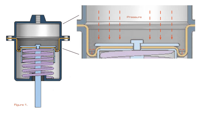
Figure 1 illustrates pressure reaction on the diaphragm. It can be seen that almost the entire pressure load is supported by the piston head and only a small amount of the liquid or gas pressure is supported by the narrow convolution of the diaphragm. Also note in Figure 1 that the lines of unit pressure (acting in horizontal planes because they must be normal to the surface) force the diaphragm against the piston and cylinder sidewalls on that portion of the diaphragm in contact with the cylinder wall and piston skirt.
The lines of force acting on that part of the diaphragm not in contact with the cylinder or piston skirt (the semicircular segment of the convolution) are shown in Figure 2.
Each line of unit pressure (Pr) acts normal to the semicircular segment; thus any one of the pressure lines can be replaced by its horizontal and vertical component. The horizontal components, acting in opposition, cancel out each other.
The sum of the vertical components of the unit pressures acting on this semicircular segment add up to the total pressure force (F) and is equal to the normal pressure on the projection of this segment.
Considering a unit (1 inch) of circumferential length of the diaphragm, the foregoing is:
The total force F is supported equally by the fabric reinforcement of the diaphragm on the piston and cylinder wall (see Figure 2). Therefore tension force FT (lbs.) in either wall is simply one-half the value of F or
Where FT is the tension force on the diaphragm sidewall for each unit of circumferential length. Since tensile force FT and fabric stress SF are identical, equation 4 can be expressed in terms of fabric stress:
Fabric stress can be computed using equation 5. For example, if a 3¬inch diameter diaphragm with an effective pressure area of 6.35 sq. in. and a convolution width of .156 is subjected to a loading pressure of 100 psi, the resulting total thrust is 635 lbs. However, fabric stress on the narrow convolution is only:
Fabric materials are available in tensile strengths greater than 7.8 lbs. per inch. Therefore the very narrow convolution widths with resulting low stress values in the fabric fibres enable diaphragms to be used in applications involving high working pressures.
In effect, DiaCom Rolling Diaphragms are pressure vessels having a variable volume and flexible moving sidewalls. As in any other pressure vessel, its strength should be considered with respect to safety factors. Generally, diaphragms can be designed with a large safety factor. In effect, this means the maximum safe working pressure will be a fraction of the pressure that would cause failure in the convolution area. (In some aircraft applications where working pressures are as high as 1000 psi and total cycle requirements are low, safety factors are substantially increased.)
Actual stress analysis and selection of fabrics will be recommended by the DiaCom engineering department for each application.
For Product Inquiries & Information Only: