Diaphragm Life Design Considerations
Observing prudent guidelines can greatly extend service cycles
When designing a diaphragm, always consider what can be done to extend the life of the part. When you know the inherent weaknesses of diaphragms and then design accordingly, the likelihood of successful applications soars.
The chief contributing factors to premature failure of a diaphragm are:
- Burrs and sharp edges
- Abrasion
- Back pressure
- Circumferential compression
Smooth the way with proper hardware
Clearly, the first step is in the hardware design itself. The obvious considerations are the elimination of burrs and sharp edges that may come in contact with the diaphragm. Even seemingly minor flaws can cut and tear at both fabric and elastomer, resulting in premature failure.
The smoother the surface, the better
Not so obvious is the relative smoothness of the hardware's finish. When pressure is constantly applied then relieved, the diaphragm does rub against the supporting hardware. If the surface of the hardware is rough, it can abrade the fabric causing an earlier than expected failure.

How smooth is smooth enough?
It is recommended that these surfaces be no rougher than 32 micro inches and if necessary be finished to 16 micro inches in higher-cycle applications. Although diaphragms do not require lubrication, they may be coated with a molybdenum disulfide prior to installation to help reduce abrasion. The piston may also be coated with Teflon® to reduce friction when the diaphragm shifts against it, or with an elastomer coating, which helps prevent abrasion by preventing the diaphragm from shifting.
Proper alignment and manageable back pressure
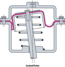
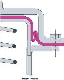
The quickest failure occurs when the sidewall of the diaphragm comes in contact with itself. When this happens, the two rubber surfaces lock together while the piston continues to travel. This generally results in the sidewall of the diaphragm being jammed between the piston and cylinder wall, resulting in the elastomer and fabric being torn. There are generally two causes for this.

1. The first is the alignment between the piston and cylinder . There is usually no problem at high pressure where the pressure itself equalises on the diaphragm, helping to center the piston. However at low pressure, gravity can take over and pull the piston to one side, causing a problem. This can be avoided with a bushing for the piston or some other way of keeping the piston centred throughout its stroke.
2. The second cause of this type of failure is back pressure. Generally, a diaphragm can take a high differential in only one direction. If the pressure gets higher on the low pressure side of the diaphragm, the sidewall collapses, causing failure. The problems with back pressure usually occur when the user is unaware that it even exists. Since most diaphragm applications are in closed actuators, there must be a means to adjust for the change in gas or fluid volume above and below the diaphragm as it is stroked up and down.
Back pressure: Beware of the one-way street
Stress is usually not a problem on the high-pressure side of the diaphragm because changes in volume determine in large part the function of the apparatus. Typically, back pressure problems occur on the low-pressure side where the volume of gas or fluid must be removed and replaced with each stroke of the diaphragm.
Alleviating back pressure through ventilation
Vent holes must be sized correctly to allow enough volume to pass through in the precise amount of time it takes to stroke the diaphragm. It is also important to remember this when actuation sequences are increased during accelerated testing or whenever the device is under a higher load of stress or more rapid cycling.
Corner the dangers of sidewall compression
The final cause of failure is circumferential compression. This is a term used to describe the larger diameter sections of the diaphragm sidewall being compressed around the piston. This results in the sidewall forming an axial fold in to sidewall to allow the diaphragm to conform to the piston. Because the fabric used for support has a square pattern, the folds occur at the four points that the warp and fill threads are perpendicular to the convolution.
Minimizing the chance of rupture
Circumferential compression is most often referred to as “four cornering.” It is not something that can be totally eliminated but rather controlled. The continuous folding at the same location eventually leads to a break in cross thread, leading to a rupture of the elastomer.
Ways to reduce circumferential compression
There are several ways to reduce this circumferential compression. Each has its advantages and drawbacks. Our engineers can recommend what's best for you.
1. Limit the stroke, limit the stress
The first way is to use only the bottom half of the diaphragm's stroke. Using the bottom half of the stroke limits the section of the sidewall that must be compressed around the piston to the top. This is the section of the sidewall with the smallest circumference difference with the piston, which means the folds will be smaller and not as sharp. The result of this is longer diaphragm life.
2. Double tapering eases compression
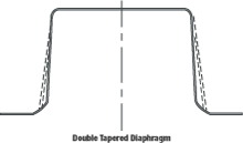
Another way to reduce circumferential compression—and still keep the total stroke capability of the diaphragm—is the double tapered diaphragm.
On a standard “top hat” diaphragm, the sidewall of the diaphragm is a straight line tangent to the flange and piston radii.

On a double tapered top hat, the sidewall is a line tangent to the cylinder radius running at a 45 to 60 degree angle to a point approximately 60 percent of the way through the convolution width.
At this point it wraps around a small radius then straight to a point tangent to the piston radius. This makes the sidewall at a much steeper angle for the usable length of the sidewall, which in turn reduces the circumference.
3. “Pre-convolution” anticipates the problem
The same effect can be obtained in a pre-convoluted diaphragm by molding the diaphragm as an offset pre-convoluted diaphragm. Simply put, this is a pre-convoluted diaghragm molded in the full up position. The benefit is clear: it puts the total amount of working sidewall at the piston circumference, virtually eliminating circumferential compression.
4. Hardware tapering: A risky compromise
The final means of reducing the circumferential compression is with a tapered piston. This simply increases the piston circumference as the sidewall circumference increases. Despite the benefit of adjusting the circumference, this is probably the least dersirable means to solving the compression problem for two obvious reasons:
- Circumference adjustment resulting from tapering decreases the effective pressure as the pressure rises. (Tapering decreases overall effective pressure as pressures rise.)
- Tightening the convolution increases the effective pressure as pressure decreases.
Both pressure-related effects must be thoroughly considered—and tested—before this solution is used.
For Product Inquiries & Information Only:

